WelshGas
Retired after 42 yrs and enjoying Life.
Super Poster
Lifetime VIP Member
Buy all your VW California Accessories at the Club Shop Visit Shop
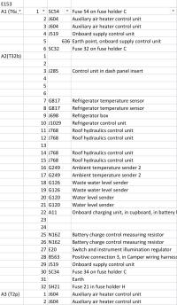
I can tell you all the control panel feeds pin by pin and the roof ECUs ones.Andrew, thank you for the info. I tried putting a signal on the terminals you suggested. Just put the 12 volt signal without a negative as I assumed the negative earth connection would already be on the tbx plug and J768 unit. With and without the ignition on. There seems to be multiple feeds to the control panel and J768 snd still trying to figure them out, all fuse are ok. Big job but I am trying to trace all the wires and draw my own circuit diagram.the roof did open and close satisfactorily by putting 12v on the 2 pin plug directly connected to hydraulic motor.
Des
I can tell you all the control panel feeds pin by pin and the roof ECUs ones.
But in Terms of the Roof ECU and Control Panel.
There are only the four wires that the control panel uses for the roof control as above, the rest are related to everything else, water, heater, fridge, battery sensing.
The Roof ECU has separate ign and permanent power feeds, it has its own Earth connection and the other 6 connections are to the roof sensors. 4 x sensor inputs and 2 sensor power outputs. Then the pump output which is reversible relay output (H-Bridge) and also has a current shunt to measure the pump load.

The square boxes with numbers mean that the circuits cross into another page.Hi again, had another try putting 12v feed onto the 23 pin to open and onto 22 to close. The roof went through the full sequence as if operating from the control panel, complete with the slight overrun of the pump in each direction to lock the roof in place. The difference this time was I checked the feeds from the fuses under the passenger seat, I had to override the 100 relay that controls the main feed to those fuses. Don’t know yet the control 0.35 black wire was’t providing the control feed ( may be because the E153 plug was not plugged in the the control panel) but as soon as they (the fuses) wire live then the roof worked as stated above.
One other question is: on the electrical schematic what are the rectangular block with a number, 20 43 etc, there is no plug reference number or terminal rail they my be on. I need understand this to complete my overall circuit diagram.
Thanks that makes it easier to follow the diagram. The one I am using is from post 1946vw.co.uk/vw….The square boxes with numbers mean that the circuits cross into another page.
So within the same section, you look at the number, then look at the numbers on the bottom of the sheet and go to the page that has that number
Often with Power feeds it is easier to just use the Fuse box charts in the back and work backwards.
So on the Roof diagram, you have 23 and 43.
[23] is the Ign feed from fuse SC55 this also feeds the control panel E153 (T32b/32)
[43] is the Perm feed from Fuse SH17
If you just want to use the control wires from the panel, then the wiring to J768 should not need to be touched.
Andrew
The VW California Club is the worlds largest resource for all owners and enthusiasts of VW California campervans.

